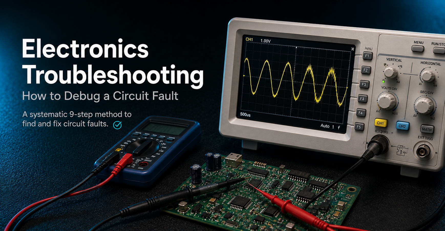
When an electronic circuit doesn't behave as expected, replacing components at random is rarely the fastest way to find the problem.
Electronics troubleshooting is a structured process of narrowing down why a circuit is not behaving as designed. The goal is to define the fault precisely, reproduce it, inspect the board, divide the circuit into functional blocks, verify power, and then trace signals until the measurements stop matching expectations.
Whether you're debugging a simple LED circuit or a complex embedded board, a systematic approach can turn hours of guesswork into a repeatable diagnostic process.
What Does Circuit Debugging Involve?
Circuit debugging is the process of methodically determining why a circuit is:
Completely dead
Behaving incorrectly
Communicating incorrectly
Unstable
Overheating
Failing intermittently
Working initially but failing after extended operation
The key principle is simple:
Debugging is not guesswork. Every measurement should eliminate possible causes and narrow the search.
For example, if an IC's supply voltage is correct but its output is incorrect, you have already eliminated several potential causes. If the supply voltage itself is missing, there's no reason to start investigating the IC's firmware or signal processing yet.
This is why troubleshooting should generally move from fundamentals to complexity.
Equipment Required for Circuit Troubleshooting
You don't need an enormous collection of laboratory equipment to diagnose most circuit faults. A practical electronics troubleshooting bench should include the following:
Equipment | Primary Use |
|---|---|
Digital Multimeter | Voltage, resistance, continuity, and basic electrical measurements |
Oscilloscope | Waveform shape, timing, noise, and signal integrity |
Bench Power Supply | Controlled power with adjustable current limiting |
Logic Analyser | Digital signals and communication buses |
Magnifying Glass / USB Microscope | Inspecting solder joints, components, and PCB damage |
Schematic & PCB Layout | Understanding circuit connections and locating test points |
Notebook / Spreadsheet | Recording test points, expected values, and actual measurements |
The tools are important, but the method you use them with is even more important.
The Electronics Troubleshooting Workflow
A reliable troubleshooting process can be broken down into nine steps.
Step 1: Define the Problem Precisely
Start by describing exactly what is wrong.
Avoid vague statements such as:
"The circuit doesn't work."
Instead, describe the expected behavior and what actually happens.
For example:
"The LED should illuminate when the button is pressed, but it remains off."
A precise problem statement gives you something measurable to test.
Record:
What should happen?
What actually happens?
When does the problem occur?
Does it happen every time?
Which functions still work?
The clearer the problem definition, the smaller your troubleshooting search space becomes.
Step 2: Reproduce the Fault Reliably
Before trying to fix anything, determine whether you can reproduce the failure.
If the circuit fails consistently, diagnosis is usually straightforward.
Intermittent faults are more difficult.
Record environmental or operating conditions that appear to trigger the problem:
Temperature
Movement
Vibration
Timing
Load
Power conditions
Cable movement
If you can reliably trigger the fault, you can monitor the circuit while it happens.
Step 3: Inspect the Board Visually
Before connecting instruments or replacing components, inspect the PCB.
A visual inspection can reveal surprisingly many problems.
Look for:
Cold solder joints
Solder bridges
Burnt components
Bent pins
Reversed components
Loose connectors
Damaged PCB traces
Missing components
Physical damage
Use a magnifying glass or USB microscope when working with small surface-mount components.
A five-minute visual inspection can sometimes eliminate hours of unnecessary electrical testing.
Step 4: Divide the Circuit Into Functional Blocks
Don't immediately treat the entire circuit as one system.
Break it into functional sections.
A typical embedded circuit might look like:
Power Supply
     ↓
Input Stage
     ↓
Processing / Microcontroller
     ↓
Output Stage
     ↓
Load
Each block can then be tested independently.
For example, if the power supply is producing the correct voltage but the microcontroller is not responding, you can focus your investigation on the processing stage instead of testing every component on the board.
This is commonly known as the divide-and-conquer approach.
Step 5: Verify Power First, Always
One of the most important troubleshooting rules is:
Check the power before blaming the component.
Verify that each major circuit stage receives the expected supply voltage.
Start at the power connector and work forward through the circuit:
Power Connector
      ↓
Protection
      ↓
Fuse
      ↓
Regulator
      ↓
IC Supply Pin
      ↓
Functional Circuit
If the expected voltage exists at one point but disappears at the next, the fault is somewhere between those two points.
A significant number of apparently complex circuit failures can ultimately be traced back to:
Missing power
Incorrect voltage
A blown protection component
A short circuit
Poor grounding
An unstable supply
Step 6: Trace the Signal From Source to Destination
Once power has been verified, follow the signal through the circuit.
For an analogue circuit, this may involve measuring voltage at different stages.
For a digital circuit, an oscilloscope or logic analyser can show whether the expected transitions and timing are present.
The basic approach is:
Signal Source
     ↓
Stage 1
     ↓
Stage 2
     ↓
Stage 3
     ↓
Destination
Continue measuring until the signal no longer matches the expected behavior.
The point where the signal changes from correct → incorrect gives you a much smaller area to investigate.
Step 7: Isolate Suspect Components
Once you've identified the suspicious section, isolate individual components.
Depending on the circuit, this may involve:
Removing a component
Lifting one component leg
Disconnecting a section
Substituting a known-good component
Testing the surrounding circuit independently
The objective is to determine whether the suspected component is actually responsible for the fault.
Don't automatically replace a component simply because it looks suspicious.
Use measurements to support the diagnosis.
Step 8: Change One Variable at a Time
This is one of the most important habits in electronics debugging.
If you simultaneously:
Replace an IC
Change a resistor
Reflow several solder joints
Replace a capacitor
Modify firmware
and the circuit suddenly works, you don't know what actually fixed it.
Instead:
Make one change.
Retest.
Record the result.
Make the next change only if necessary.
This keeps the troubleshooting process measurable and reproducible.
Step 9: Confirm the Fix and Retest Fully
Finding something that appears to fix the problem isn't the final step.
Retest the complete circuit.
Verify:
Normal operation
All inputs
All outputs
Communication
Different operating conditions
Extended operation where relevant
One fault can sometimes hide another.
A proper repair isn't complete until the complete system has been tested again.
Eight Common Circuit Faults and Their Fixes
Many electronics failures fall into a relatively small number of categories.
The following table provides a practical starting point when diagnosing common circuit problems.
Symptom | Likely Cause | Recommended Fix |
|---|---|---|
Board entirely dead | No input power, blown protection component, or major short | Measure at the power connector, then work forward through fuses, protection components, and the regulator |
Works intermittently | Fractured solder joint, loose connector, marginal supply, or noise | Reproduce the fault, monitor suspect areas, inspect/rework the joint, and retest |
Component runs hot | Wrong value, reversed orientation, or short on its output | Power off immediately, verify the component against the schematic, and check downstream for shorts |
Microcontroller will not boot | Missing clock, incorrect reset state, power sequencing issue, or firmware problem | Verify clock and reset conditions, confirm power, then reprogram if appropriate |
I2C, SPI, or UART not communicating | Missing pull-ups, incorrect baud rate, incorrect wiring, or missing shared ground | Check signal levels and timing with a logic analyser and confirm a common ground |
Signal has the wrong shape | Incorrect decoupling, poor grounding, or unstable supply | Add appropriate decoupling close to IC power pins and verify supply stability under load |
Fails once enclosed | Mechanical stress, interference, or enclosure-related grounding | Check for pinched wiring and retest using the final routing and grounding arrangement |
Fails after prolonged operation | Thermal drift, heat-related joint changes, or capacitor degradation | Monitor temperatures during extended operation and retest suspect components when hot |
Fault: The Board Is Completely Dead
When a board shows no signs of operation, start at the power connector.
Don't immediately assume the microcontroller has failed.
Check the path systematically:
Power Input
    ↓
Fuse / Protection
    ↓
Protection Diode
    ↓
Voltage Regulator
    ↓
Supply Rail
    ↓
IC Power Pins
Measure the voltage at each stage.
If the voltage is correct at one point but missing at the next, you've narrowed the problem to that section.
Fault: The Circuit Works Intermittently
Intermittent problems can be among the most frustrating circuit faults.
Possible causes include:
Cracked solder joints
Loose connectors
Marginal power supplies
Electrical noise
Mechanical stress
Try to reproduce the fault deliberately.
Monitor the circuit while gently manipulating the suspect area and inspect questionable joints under magnification.
Once the fault is reproduced, repair the suspected connection and retest.
Fault: A Component Gets Hot
An unexpectedly hot component should be treated seriously.
Possible causes include:
Incorrect component value
Reversed component orientation
Excessive current
Short circuit
Incorrect supply voltage
Important
Turn the power off before continuing to investigate.
Then compare the component against the schematic and inspect the circuit downstream for shorts or incorrect connections.
Fault: The Microcontroller Will Not Boot
A microcontroller that doesn't boot can have several possible causes.
Check the fundamentals first:
Supply voltage
Ground connection
Reset state
Clock source
Power sequencing
Firmware
Use the relevant device documentation to verify the expected clock and reset conditions.
If the hardware checks out, reprogramming the device can help determine whether the problem is related to the firmware.
Fault: I2C, SPI, or UART Is Not Communicating
Communication problems often originate from relatively simple issues.
Check:
Wiring
Signal levels
Ground connections
Pull-up resistors where required
Baud rate
Clock timing
Chip-select configuration
Communication sequence
A logic analyser is particularly useful for identifying whether the expected communication signals are actually being generated.
For example:
Microcontroller
      │
      ├── SDA / MOSI
      ├── SCL / SCLK
      ├── TX / RX
      └── GND
             ↓
         Peripheral
Always verify that the communicating devices have a suitable common ground reference.
Fault: The Signal Is Present but Has the Wrong Shape
Sometimes a signal exists, but its waveform is not what you expect.
Possible causes include:
Poor grounding
Insufficient decoupling
Unstable supply
Noise
Signal integrity problems
An oscilloscope can reveal problems that a multimeter cannot.
Inspect the waveform and compare it with the expected signal.
Also verify that decoupling capacitors are located appropriately close to the IC power pins and that the supply remains stable when the circuit is under load.
Fault: The Circuit Fails After It Is Enclosed
A circuit that works on the bench but fails after assembly may have a mechanical or environmental problem rather than a fundamental circuit-design problem.
Check for:
Pinched wires
Connector movement
Mechanical pressure on the PCB
Changed grounding paths
Interference introduced by the enclosure
Retest the circuit using the final physical routing and grounding configuration.
Fault: The Circuit Fails After Running for a Long Time
If a circuit works initially but fails after extended operation, investigate temperature and component aging.
Possible causes include:
Thermal drift
Solder joints changing behavior as they heat
Capacitor degradation
Components operating outside their intended temperature range
Monitor the temperature of suspect components while the circuit is running.
Then repeat measurements while the board is hot.
Debugging Best Practices
Good troubleshooting isn't just about having the right equipment. It's also about developing a disciplined process.
1. Start With the Simplest Explanation
Check power, ground, connectors, and obvious physical problems before investigating complicated causes.
2. Keep a Troubleshooting Log
Write down:
Test point
Expected value
Measured value
Test condition
Result
This prevents you from repeating the same tests and provides a record of what has already been eliminated.
3. Trust Measurements Over Assumptions
If a measurement doesn't match your expectation, investigate it.
Don't dismiss an unexpected reading simply because the circuit "should" be working differently.
4. Divide and Conquer
Instead of testing every component individually, divide the circuit into functional sections.
Testing the midpoint of a signal chain can eliminate large portions of the circuit from consideration.
5. Change Only One Thing at a Time
If you make several changes simultaneously, you lose the ability to determine which change actually solved the problem.
Equip Your Electronics Troubleshooting Bench
A practical troubleshooting setup doesn't have to be enormous.
A digital multimeter, current-limited bench power supply, oscilloscope, and logic analyser cover a large portion of common electronics debugging tasks.
The right combination depends on the type of circuits you're working with.
For component-level measurements, start with a multimeter.
For power behavior and analogue signals, move to an oscilloscope.
For digital buses and communication protocols, a logic analyser can quickly reveal timing and protocol problems.
The Divide-and-Conquer Method
The divide-and-conquer method is especially powerful for complex circuits.
Imagine a signal passing through eight stages:
Source
  ↓
Stage 1
  ↓
Stage 2
  ↓
Stage 3
  ↓
Stage 4
  ↓
Stage 5
  ↓
Stage 6
  ↓
Stage 7
  ↓
Destination
Instead of testing every stage sequentially, test somewhere near the middle. If the signal is correct at Stage 4, the first four stages are likely functioning correctly. You can then focus on the remaining stages. This dramatically reduces the number of measurements needed to locate a fault.
The goal of troubleshooting isn't to test everything. It's to eliminate the largest number of possibilities with the fewest useful measurements.
Frequently Asked Questions
Where Should Troubleshooting Begin on a Dead Board?
Start at the power connector. Confirm that the input voltage reaches the board, then measure forward through the fuse, protection components, and regulator. Continue until the expected voltage disappears. The fault is generally somewhere between the last correct measurement and the first incorrect one.
How Can You Locate an Intermittent Fault?
First, reproduce the fault deliberately. Then monitor the circuit while testing the conditions that appear to trigger the failure. Depending on the situation, gently flexing the board, applying controlled heat, or using freeze spray can help expose a temperature- or mechanically-sensitive fault. Always use appropriate precautions when applying heat or cold to electronics.
What Is the Divide-and-Conquer Method?
The divide-and-conquer method means testing a circuit at strategic points rather than checking every component one after another. For a signal chain, measuring the midpoint can tell you whether the problem is before or after that point. Each useful measurement can therefore eliminate a large portion of the remaining search area.
Should You Replace a Component If It Looks Suspicious?
Not automatically.
Visual inspection is valuable, but a component that looks normal can still be faulty, while a component that looks unusual may still be operating correctly.
Use measurements, the schematic, and controlled substitution to confirm the diagnosis.
Final Thoughts
Effective electronics troubleshooting is less about having a sixth sense for circuit failures and more about following a disciplined process.
Start by defining the problem. Reproduce it. Inspect the hardware. Break the circuit into functional blocks. Verify power first. Then trace the signal until the expected behavior disappears.
From there, isolate the suspect section, change one variable at a time, and fully retest the repaired circuit.
When debugging becomes frustrating, return to the fundamentals:
Check the power. Check the ground. Check the connections. Then follow the signal.
A significant number of seemingly mysterious circuit faults become much easier to solve once these basics are systematically verified.