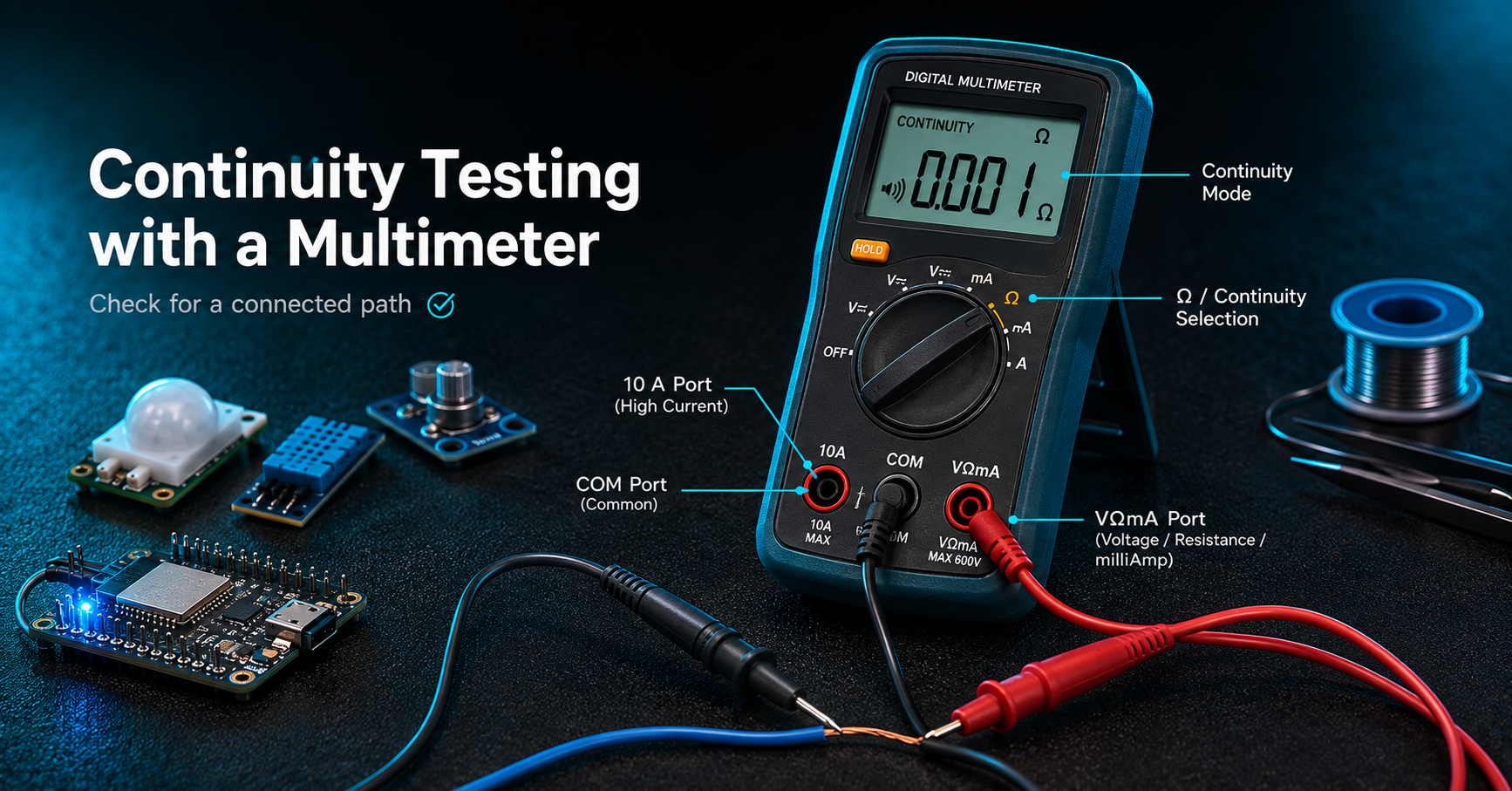
A digital multimeter is the primary diagnostic instrument in electronics. It measures voltage, current and resistance, and most models also test continuity, diodes and capacitance. Used correctly it confirms in seconds what would otherwise be guesswork, which is why it is the first instrument students and engineers alike reach for.
Parts of a Digital Multimeter
• Display presents the measured value and its unit.
• Selector dial chooses the measurement function.
• COM port the black probe connects here for every measurement.
• VΩmA port the red probe connects here for voltage, resistance and small currents.
• 10 A port the red probe moves here only for larger currents.
• Probes red for the positive reference, black for common.
How to Measure with a Multimeter?
1. Voltage (DC or AC)
Select DCV for batteries and regulated supplies, or ACV for mains. With the black probe in COM and the red in VΩmA, place the probes in parallel across the two points, red to positive.
2. Resistance
Select the ohms range. Power down the circuit and, where possible, lift one leg of the component, since parallel paths distort the reading. Touch the probes to the component's two leads.
3. Continuity
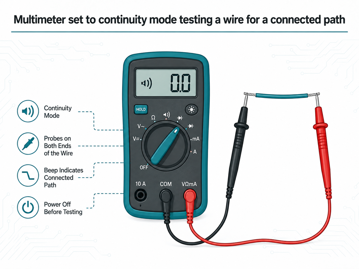
Select continuity mode. With power off, touch the probes to both ends of the conductor. A beep confirms an electrically connected path.
4. Current
Select DCA or ACA and move the red probe to the mA or 10 A port according to the expected current. Break the circuit and connect the meter in series; current cannot be measured in parallel as voltage is.
5. Diode Test
Select the diode symbol. Red on the anode and black on the cathode should show a forward drop of approximately 0.5 to 0.7 V for silicon. Reversed, the display should read open.
6. Capacitance
Select the capacitance range. Discharge the capacitor fully, observe polarity on electrolytic types, then connect it to the designated terminals.
Common Multimeter Problems and Their Fixes
Symptom | Likely cause | Fix |
Reads 0 or OL unexpectedly | Wrong function, wrong ports, or an unsuitable manual range | Confirm the dial setting and port selection, then step the range |
Blank or frozen display | Depleted battery, blown internal fuse, or a loose probe | Replace the battery, then check the fuse and probe seating |
Voltage reading fluctuates | Poor probe contact, a noisy source, or a switching circuit | Press firmly on clean metal and measure closer to the source |
Resistance value looks wrong | Component still in circuit, or oxidised probe tips | Lift one leg to isolate the component and clean the tips |
Fuse blows after a current test | Connected in parallel while in current mode, or the limit was exceeded | Fit the exact fuse specified and always connect in series |
No beep on a good conductor | Resistance exceeds the continuity threshold on long or thin wire | Use the resistance range and accept a near-zero value |
AC reading looks incorrect | An average-responding meter measuring a non-sinusoidal waveform | Use a true-RMS meter, or verify with an oscilloscope |
Reading changes when leads move | A fractured conductor inside the probe lead | Test across a known resistor while flexing, then replace the leads |
How to Choose a Digital Multimeter
Five specifications determine whether a meter suits the work.
• CAT rating: CAT II suits benchtop electronics; CAT III or IV is required for mains and installation work. Probes must carry the same rating as the meter.
• True-RMS: necessary for accurate readings on the distorted waveforms from dimmers, motor drives and switching supplies.
• Auto-ranging: faster and safer for students; manual ranging offers the control experienced users often prefer.
• Count and resolution: a 6000-count display resolves finer differences than a 2000-count model.
• Fused current inputs: confirm that both current inputs are protected by correctly rated HRC fuses.
An auto-ranging CAT III true-RMS meter with a 6000-count display covers every measurement described above.
Ready to buy? Compare true-RMS and auto-ranging models, spare probe sets and replacement fuses in our multimeters range. |
Safety Precautions
• Never measure current with the dial set to voltage, or the reverse.
• Begin on the highest range when the voltage is unknown on a manual-range meter.
• Never measure resistance or continuity on a live circuit.
• Match the CAT rating of both meter and probes to the environment.
• Keep fingers behind the probe guards when working at higher voltages.
Frequently Asked Questions
1. How do you test a battery with a multimeter?
Select a DCV range above the battery's nominal voltage, place the red probe on the positive terminal, the black on the negative. A 1.5 V alkaline cell reading below approximately 1.3 V is depleted.
2. Why does a multimeter display OL?
OL indicates over-range or an open circuit: either the value exceeds the selected range, or no conductive path exists between the probes.
3. Can a multimeter measure voltage and current simultaneously?
No. Voltage is measured in parallel and current in series, so each requires a different connection to the circuit.
Tip: when a reading appears implausible, verify the instrument before the circuit. Measure a fresh battery or marked resistor to confirm the meter works.