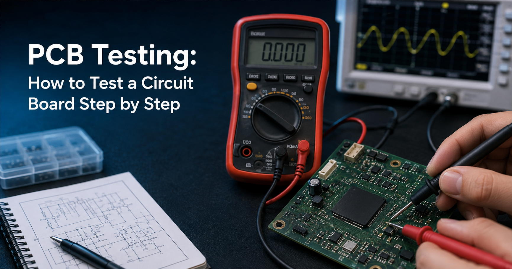
PCB testing verifies a circuit board's connections and behaviour before and after power is applied. Run the checks in sequence: visual inspection, flux cleaning, a continuity test, a VCC-to-GND short check, a current-limited power-up, voltage readings at the test points, signal verification on an oscilloscope, and a thermal check.
What Is PCB Testing?
PCB testing is the process of checking a printed circuit board, before or after soldering, to confirm that every connection is correct, that no shorts or opens exist, and that the board functions as the schematic intends. Bare-board testing verifies the copper before assembly; this guide covers assembled-board testing, also called PCBA testing.
Tools Needed:
• Digital multimeter with continuity and resistance modes
• Bench power supply with an adjustable current limit
• Oscilloscope or logic analyser for signal and timing checks
• Magnifying glass or USB microscope
• Isopropyl alcohol and a soft brush
• Schematic, layout and datasheets for the board
• Anti-static wrist strap, per ANSI/ESD S20.20
Types of PCB Testing
Method | What it catches | Typical stage |
Visual and AOI | Bridges, tombstoning, reversed or missing parts | First, always |
Bench testing | Shorts, opens, wrong voltages, dead signals | Bring-up and repair |
Flying probe | Opens, shorts, wrong component values | Low volume |
In-circuit test (ICT) | Component faults across the whole board | High volume |
Boundary scan (JTAG) | Interconnect faults, including under BGAs | Dense digital boards |
Functional test | Whether the board performs its intended task | Final, before shipping |
PCB Testing Process
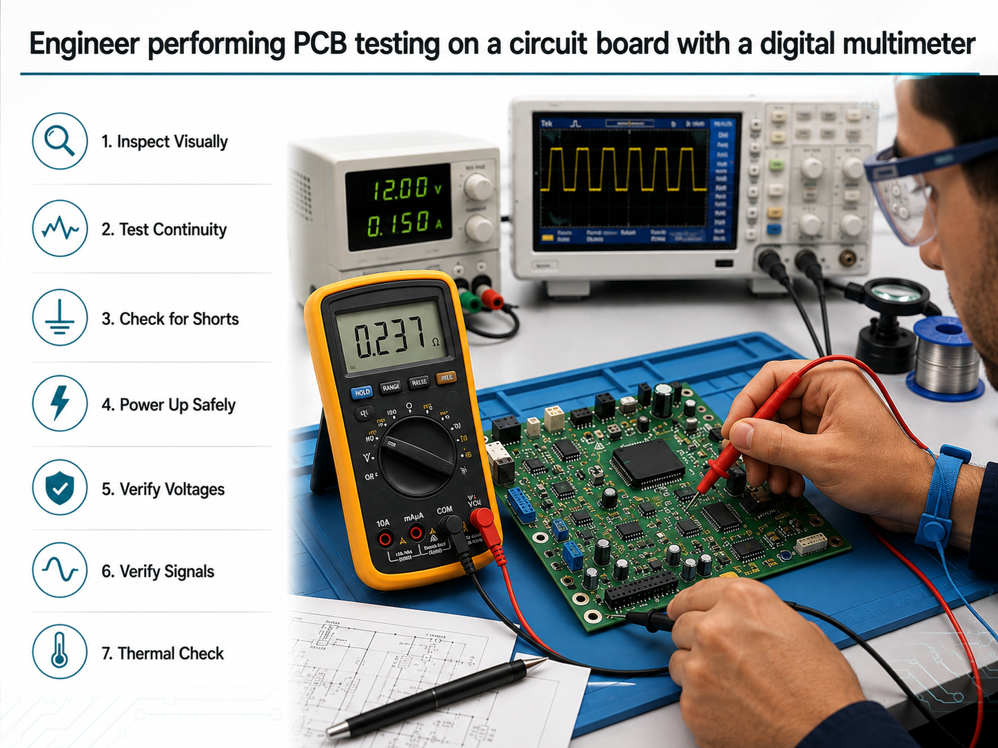
1. Inspect visually: Check under magnification for cold joints, solder bridges, missing or tombstoned parts and reversed polarity. Acceptance criteria are set out in IPC-A-610.
2. Clean the board: Remove flux with isopropyl alcohol and a soft brush, then dry fully. Residue causes false continuity readings.
3. Test continuity unpowered: Confirm connected nets beep and isolated nets do not. Probe at the pads so the solder joint is included.
4. Check the rails for shorts: Measure resistance between each supply rail and ground. A near-zero reading is a short to fix first.
5. Power up current-limited: Set the limit well below the expected draw, then raise the voltage while watching the current.
6. Measure the test points: Compare regulator outputs and IC power pins against the schematic, keeping the black probe on a fixed ground.
7. Verify the signals: Confirm clock frequency, amplitude and timing on an oscilloscope, starting at the clock source.
8. Run a thermal check: After several minutes, find any component running hotter than expected, without touching bare metal.
Common PCB Faults and Their Fixes
Symptom | Likely cause | Fix |
Near-zero resistance, VCC to GND | Solder bridge, reversed part, or a board defect | Inspect for bridges first, then check orientation by section |
No continuity on a connected net | Cracked trace, cold joint, or an unplated via | Reflow the nearby joints; jumper a broken trace |
Component heats immediately | Wrong value, reversed polarity, or a shorted output | Power off, verify orientation and value, check downstream |
Current draw far above design | A short, or a part installed backwards | Keep the limit low and hunt section by section |
Test point reads 0 V or wrong | No regulator input, a failed part upstream, or a broken trace | Work back toward the source until the voltage returns |
No signal on the oscilloscope | Source unpowered, broken connection, or a floating ground clip | Check the probe and ground clip, then power at the source IC |
Intermittent operation | Fractured joint, loose connector, or a marginal supply | Flex the board while monitoring a suspect joint, then reflow |
False continuity, no visible bridge | Conductive flux residue bridging the measurement | Clean with isopropyl alcohol, dry fully, retest |
Choosing PCB Test Equipment
Three instruments cover the whole process.
• Digital multimeter: Continuity, resistance and DC voltage are the core functions; an auto-ranging CAT III model suffices for bench work.
• Bench power supply: The adjustable current limit matters more than any other specification. A 30 V, 5 A unit suits most boards.
• Oscilloscope: Two channels at 100 MHz handle most embedded work; a logic analyser is cheaper for purely digital signals.
Safety Precautions
• Bring a new board up on a current-limited supply.
• Verify supply polarity before connecting; reversed polarity destroys components instantly.
• Let the board cool before handling any component that ran warm.
• Wear an anti-static wrist strap and work on a grounded mat.
• Never probe a live board with tools that could slip and bridge two points.
Frequently Asked Questions
How do you test a PCB with a multimeter?
With the board unpowered, use continuity mode to verify the nets, then resistance mode between each rail and ground to rule out a short. Once powered, use DC voltage at the regulator outputs and IC power pins.
Can a circuit board be tested without applying power?
Yes, and it should be. Visual inspection, continuity testing and the rail-to-ground resistance check are all performed unpowered, and together identify most assembly faults.
What resistance should there be between VCC and GND?
There is no single correct figure, but it should be clearly non-zero, typically several hundred ohms or more. Below roughly ten ohms almost always indicates a short.
Tip: check the power rails for shorts before first power-up. This single measurement prevents most component damage during bring-up.